RTEMS on BeagleBone Black Wireless – Part 3

At the end of part 2 I was finally ready to start work on the eQEP driver for the Beaglebone Black BSP for RTEMS. As I’d mentioned previously in part 1, the BSP has been contributed to by a number of authors and it is lacking a little consistency. All the register address and bitmask #defines have ended up being dumped in the am335x.h header which makes finding things a bit of a chore. It also means that header is full of registers and bitmasks that will only ever be used by a single driver, so they don’t all need to be in a common header.

With these things in mind, when I started writing the eQEP driver, I decided I would try and keep the general API style consistent with what has already been developed in the BSP, but also try and tidy things up a bit and be a bit more consistent with the RTEMS coding conventions.

The PWM module had a function to initialise the L3 and L4_PER system clocks for a given PWMSS module, however this is something that needs to be done by any of the PWMSS functions – ePWM, eQEP or eCAP. Therefore I extracted that function and the BBB_PWMSS enum type into a new pwmss.h header and source file. I also took the opportunity to significantly simplify the implementation of the pwmss_module_clk_config function.

Next I defined my eQEP interface. It has ended up looking like the following (at the time of writing this blog post):

/**
 * @file
 *
 * @ingroup arm_beagle
 *
 * @brief eQEP (enhanced Quadrature Encoder Pulse) support API.
 */

/**
 * Copyright (c) 2020 James Fitzsimons <james.fitzsimons@gmail.com>
 *
 * The license and distribution terms for this file may be
 * found in the file LICENSE in this distribution or at
 * http://www.rtems.org/license/LICENSE.
 *
 * For details of the Enhanced Quadrature Encoder Pulse (eQEP) Module refer to
 * page 2511 of the TI Technical Reference Manual
 * (https://www.ti.com/lit/ug/spruh73q/spruh73q.pdf)
 * This driver supports using the QEP modules in Quadrature-clock Mode.
 * Direction-count Mode is not currently supported. Similarly the QEPI: Index
 * or Zero Marker and QEPS: Strobe Input pins are not currently supported.
 */

#ifndef LIBBSP_ARM_BEAGLE_QEP_H
#define LIBBSP_ARM_BEAGLE_QEP_H

#ifdef __cplusplus
extern "C" {
#endif /* __cplusplus */

#define AM335X_EQEP_REGS                       (0x00000180)
#define AM335X_EQEP_0_REGS                     (AM335X_PWMSS0_MMAP_ADDR + AM335X_EQEP_REGS)
#define AM335X_EQEP_1_REGS                     (AM335X_PWMSS1_MMAP_ADDR + AM335X_EQEP_REGS)
#define AM335X_EQEP_2_REGS                     (AM335X_PWMSS2_MMAP_ADDR + AM335X_EQEP_REGS)

/* eQEP registers of the PWMSS modules - see page 1672 of the TRM for details */
#define AM335x_EQEP_QPOSCNT       0x0   /* eQEP Position Counter */
#define AM335x_EQEP_QPOSINIT      0x4   /* eQEP Position Counter Initialization */
#define AM335x_EQEP_QPOSMAX       0x8   /* eQEP Maximum Position Count */
#define AM335x_EQEP_QPOSCMP       0xC   /* eQEP Position-Compare */
#define AM335x_EQEP_QPOSILAT      0x10  /* eQEP Index Position Latch */
#define AM335x_EQEP_QPOSSLAT      0x14  /* eQEP Strobe Position Latch */
#define AM335x_EQEP_QPOSLAT       0x18  /* eQEP Position Counter Latch */
#define AM335x_EQEP_QUTMR         0x1C  /* eQEP Unit Timer */
#define AM335x_EQEP_QUPRD         0x20  /* eQEP Unit Period */
#define AM335x_EQEP_QWDTMR        0x24  /* eQEP Watchdog Timer */
#define AM335x_EQEP_QWDPRD        0x26  /* eQEP Watchdog Period */
#define AM335x_EQEP_QDECCTL       0x28  /* eQEP Decoder Control */
#define AM335x_EQEP_QEPCTL        0x2A  /* eQEP Control */
#define AM335x_EQEP_QCAPCTL       0x2C  /* eQEP Capture Control */
#define AM335x_EQEP_QPOSCTL       0x2E  /* eQEP Position-Compare Control */
#define AM335x_EQEP_QEINT         0x30  /* eQEP Interrupt Enable */
#define AM335x_EQEP_QFLG          0x32  /* eQEP Interrupt Flag */
#define AM335x_EQEP_QCLR          0x34  /* eQEP Interrupt Clear */
#define AM335x_EQEP_QFRC          0x36  /* eQEP Interrupt Force */
#define AM335x_EQEP_QEPSTS        0x38  /* eQEP Status */
#define AM335x_EQEP_QCTMR         0x3A  /* eQEP Capture Timer */
#define AM335x_EQEP_QCPRD         0x3C  /* eQEP Capture Period */
#define AM335x_EQEP_QCTMRLAT      0x3E  /* eQEP Capture Timer Latch */
#define AM335x_EQEP_QCPRDLAT      0x40  /* eQEP Capture Period Latch */
#define AM335x_EQEP_REVID         0x5C  /* eQEP Revision ID */
/* bitmasks for eQEP registers  */
#define AM335x_EQEP_QEPCTL_UTE    (1 << 1)
#define AM335x_EQEP_QEPCTL_QCLM   (1 << 2)
#define AM335x_EQEP_QEPCTL_PHEN   (1 << 3)
#define AM335x_EQEP_QEPCTL_IEL    (1 << 4)
#define AM335x_EQEP_QEPCTL_SWI    (1 << 7)
#define AM335x_EQEP_QDECCTL_QSRC  (3 << 14)
#define AM335x_EQEP_CLK_EN        (1 << 4)
#define AM335x_EQEP_QEINT_UTO     (1 << 11)

/**
 * @brief The set of possible eQEP Position Counter Input Modes
 *
 * Enumerated type to define various modes for the eQEP module.
 */
typedef enum {
  QUADRATURE_COUNT = 0,
  DIRECTION_COUNT,
  UP_COUNT,
  DOWN_COUNT
} BBB_QEP_COUNT_MODE;

/**
 * @brief The set of possible modes for Quadrature decode
 *
 */
typedef enum {
  ABSOLUTE = 0,
  RELATIVE
} BBB_QEP_QUADRATURE_MODE;

/**
 * @brief The set of possible eQEP input pins
 *
 */
typedef enum {
  BBB_P8_11_2B_IN,
  BBB_P8_12_2A_IN,
  BBB_P8_15_2_STROBE,
  BBB_P8_16_2_IDX,
  BBB_P8_31_1_IDX,
  BBB_P8_32_1_STROBE,
  BBB_P8_33_1B_IN,
  BBB_P8_35_1A_IN,
  BBB_P8_39_2_IDX,
  BBB_P8_40_2_STROBE,
  BBB_P8_41_2A_IN,
  BBB_P8_42_2B_IN,
  BBB_P9_25_0_STROBE,
  BBB_P9_27_0B_IN,
  BBB_P9_41_0_IDX,
  BBB_P9_42_0A_IN
} bbb_qep_pin_t;


typedef struct {
  BBB_PWMSS pwmss_id;
  BBB_QEP_COUNT_MODE count_mode;
  BBB_QEP_QUADRATURE_MODE quadrature_mode;
} bbb_eqep_t;


/* The pin mux modes for the QEP input pins on the P8 and P9 headers */
#define BBB_P8_11_MUX_QEP 4
#define BBB_P8_12_MUX_QEP 4
#define BBB_P8_15_MUX_QEP 4
#define BBB_P8_16_MUX_QEP 4
#define BBB_P8_31_MUX_QEP 2
#define BBB_P8_32_MUX_QEP 2
#define BBB_P8_33_MUX_QEP 2
#define BBB_P8_35_MUX_QEP 2
#define BBB_P8_39_MUX_QEP 3
#define BBB_P8_40_MUX_QEP 3
#define BBB_P8_41_MUX_QEP 3
#define BBB_P8_42_MUX_QEP 3
#define BBB_P9_25_MUX_QEP 1
#define BBB_P9_27_MUX_QEP 1
#define BBB_P9_41_MUX_QEP 1
#define BBB_P9_42_MUX_QEP 1


/**
 * @brief This function intilizes clock for pwm sub system.
 *
 * @param PWMSS_ID It is the instance number of EPWM of pwm sub system.
 *
 * @return true if successful
 * @return false if not successful
 *
 **/

// Need to configure the CLKCONFIG register
// 5 eQEPCLKSTOP_REQ R/W 0h This bit controls the clkstop_req input to the eQEP module
// 4 eQEPCLK_EN R/W 1h This bit controls the clk_en input to the eQEP module.

// Need to read the CLKSTATUS register
// 5 eQEP_CLKSTOP_ACK R 0h This bit is the clkstop_req_ack status output of the eQEP module.
// 4 eQEP_CLK_EN_ACK R 0h This bit is the clk_en status output of the eQEP module.
rtems_status_code beagle_qep_init(bbb_eqep_t* eqep);

rtems_status_code beagle_qep_enable(BBB_PWMSS pwmss_id);

rtems_status_code beagle_qep_disable(BBB_PWMSS pwmss_id);

rtems_status_code beagle_qep_pinmux_setup(bbb_qep_pin_t pin_no, BBB_PWMSS pwm_id);

int32_t beagle_qep_get_position(BBB_PWMSS pwmss_id);

rtems_status_code beagle_qep_set_position(BBB_PWMSS pwmss_id);

rtems_status_code beagle_qep_set_count_mode(BBB_PWMSS pwmss_id, BBB_QEP_COUNT_MODE mode);

BBB_QEP_COUNT_MODE beagle_qep_get_count_mode(BBB_PWMSS pwmss_id);

uint8_t beagle_qep_get_mode(BBB_PWMSS pwmss_id);

rtems_status_code beagle_qep_set_mode(BBB_PWMSS pwmss_id, uint8_t mode);

#ifdef __cplusplus
}
#endif /* __cplusplus */

#endif /* LIBBSP_ARM_BEAGLE_QEP_H */

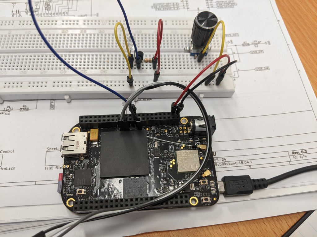
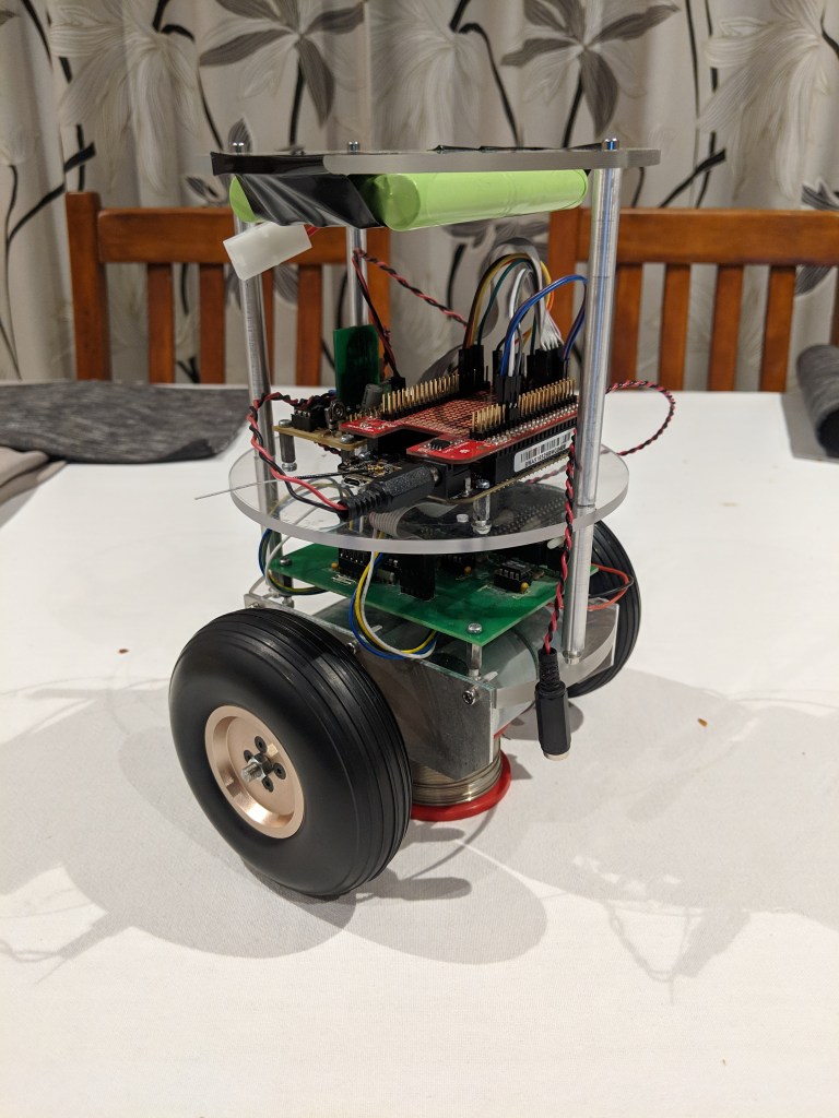
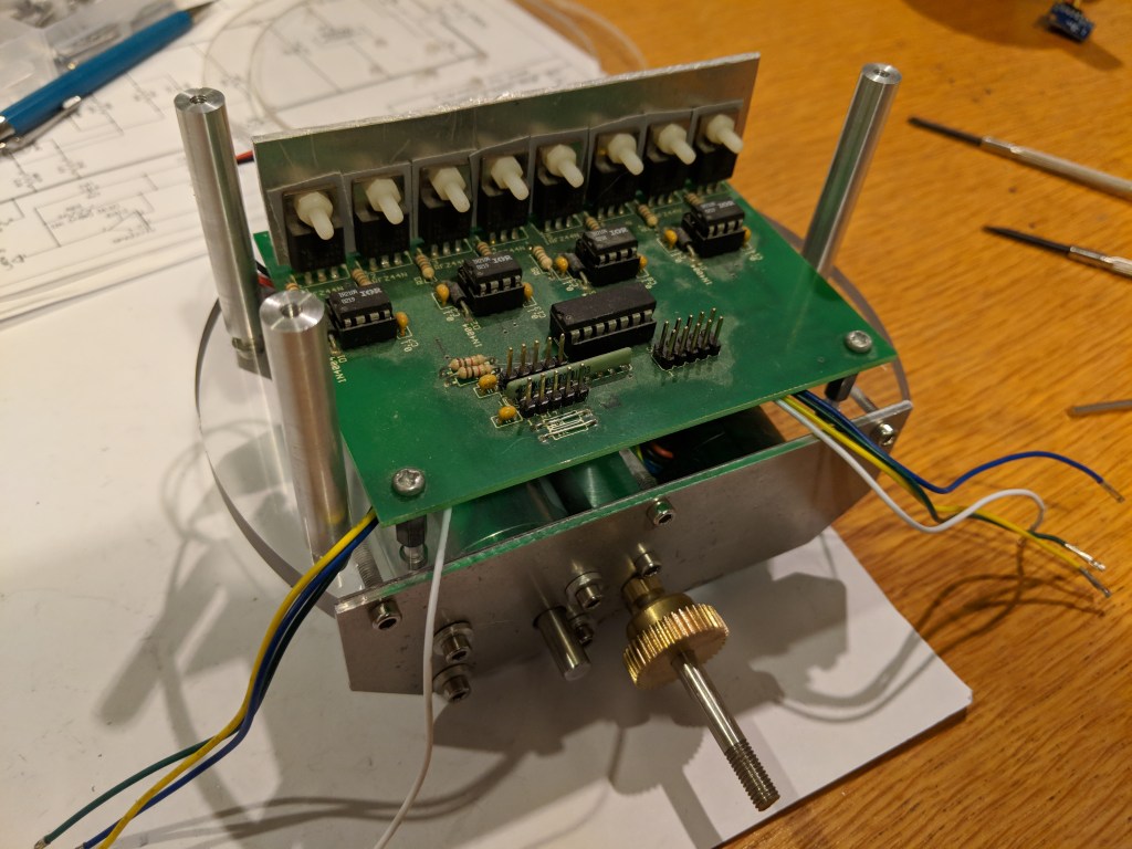
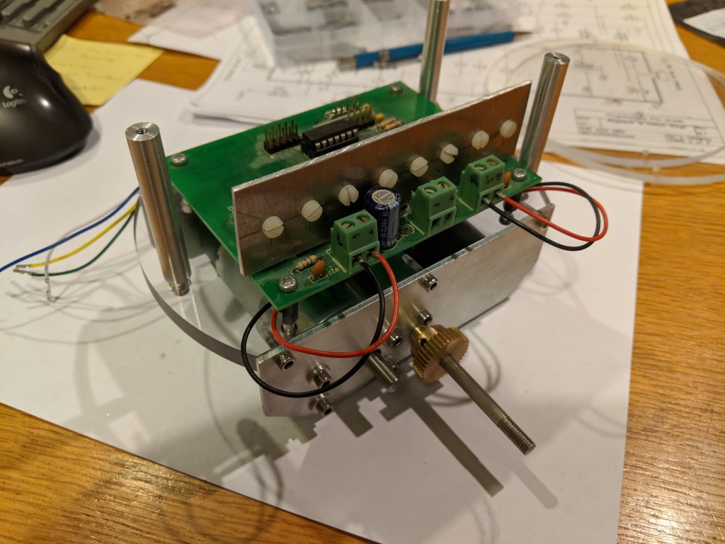
The only real snag I hit during implementation was after I had finished writing all the initialisation code and my test app and it didn’t work. I had a rotatory encoder hooked up to the BBBW and had confirmed using Linux that the hardware worked as expected.

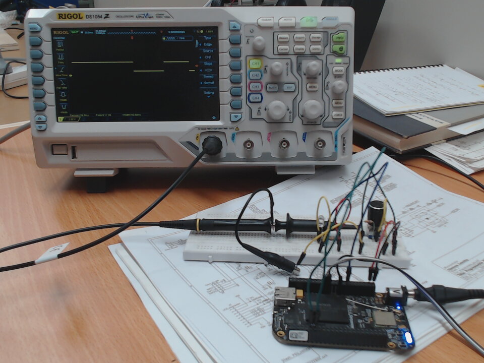
Strangely my RTEMS implementation refused to change the count value, and after running through the code several times double checking each register address and bitmask I decided to double check with Linux again. This time I also hooked my oscilloscope so I could see the pulses being generated by the encoder.

Booting back into the RTEMS code I didn’t see the encoder pulses being generated on the oscilloscope, and it didn’t take me too long to realise why. The FDT overlay that sets up the pinmux for the Linux driver enables the internal pullup resistors on the A & B input pins for the eQEP. The Linux implementation was working because the BBBW was pulling the pins up to 3.3v and the encoder was pulling them down to GND each pulse. The RTEMS implementation had put the pins in the right mux mode, but hadn’t enabled the internal pullups so the input pins were sitting at GND and no amount of turning the encoder was going to generate a pulse.

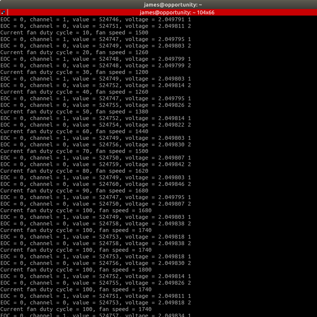
Once I’d fixed the pin configuration code it all started working! Here is a pic of the test setup and a screen shot of the terminal output to prove it.

Now that I have the basic driver working I need to tidy up the code, implement support for some of the other features and then submit a patch.

RTEMS on BeagleBone Black Wireless – Part 2

In the last post I said I was ready to start work on the eQEP driver. Well… it turned out I was a little premature declaring victory on that.

I discovered that although PWM output on P8_13 (EHRPWM2B) was working just fine, when I modified the code to use P9_14 it stopped working. After a bit more testing I discovered that all the other PWM outputs were working correctly, but P9_14 and P9_16 were a no go.

I initially went down the wrong path thinking that PWMSS1 hadn’t been initialised properly, and managed to waste an evening thinking I need to initialise it with a FDT. If I’d stopped to think things through a bit more I would have realised none of the other PWMSS modules required a FDT to set them up as the RTEMS Beaglebone PWM driver does all the hardware configuration required.

Once I got that clear in my head I worked my way through the code and found a bug in the driver. The registers that set the pin mux mode for header pins P9_14 and P9_16 were not being calculated correctly and so those pins weren’t being muxed for PWM output. I’ve submitted the following patch to the RTEMS developer list so here’s hoping that gets accepted.

bsps/arm/beagle/pwm/pwm.c | 4 ++--
 1 file changed, 2 insertions(+), 2 deletions(-)

diff --git a/bsps/arm/beagle/pwm/pwm.c b/bsps/arm/beagle/pwm/pwm.c
index 0bc5d125bf..9a346995aa 100644
--- a/bsps/arm/beagle/pwm/pwm.c
+++ b/bsps/arm/beagle/pwm/pwm.c
@@ -102,9 +102,9 @@ bool beagle_pwm_pinmux_setup(bbb_pwm_pin_t pin_no, BBB_PWMSS pwm_id)
        } else if (pin_no == BBB_P8_36_1A) {
          REG(AM335X_PADCONF_BASE + BBB_CONTROL_CONF_LCD_DATA(10)) = BBB_MUXMODE(BBB_P8_36_MUX_PWM);
        } else if (pin_no == BBB_P9_14_1A) {
-         REG(AM335X_PADCONF_BASE + BBB_CONTROL_CONF_GPMC_AD(2)) = BBB_MUXMODE(BBB_P9_14_MUX_PWM);
+         REG(AM335X_PADCONF_BASE + BBB_CONTROL_CONF_GPMC_AD(18)) = BBB_MUXMODE(BBB_P9_14_MUX_PWM);
        } else if (pin_no == BBB_P9_16_1B) {
-         REG(AM335X_PADCONF_BASE + BBB_CONTROL_CONF_GPMC_AD(3)) = BBB_MUXMODE(BBB_P9_16_MUX_PWM);
+         REG(AM335X_PADCONF_BASE + BBB_CONTROL_CONF_GPMC_AD(19)) = BBB_MUXMODE(BBB_P9_16_MUX_PWM);
        } else {
          is_valid = false;
         }
--

Now I really am ready to start working on the eQEP driver!

RTEMS on BeagleBone Black Wireless

I’ve been doing a bit of development on my balancing robot recently and have become increasingly frustrated by Linux as an embedded operating system. I love Linux and run it on my computers, and for many embedded projects it would be a great choice and with things like ssh and web server support out of the box it makes things incredibly easy to get running. However, for my robot it has started to become a bit of a hindrance. I can see clear evidence that some tasks are not being run on time, which is to be expected given the fact that Linux isn’t a real time operating system. This means that time sensitive tasks are experiencing some variability which I suspect is the cause of some of the issues I am currently experiencing.

I’ve also found it surpsingly difficult to do simple things like handle a GPIO interrupt in a way that doesn’t make programming really difficult. I’m sure there are embedded Linux developers out there that would have some simple answers for some of these issues, but for now I’m going with a move to an actual RTOS as the solution to these issues.

I’ve used RTEMS in the past on an old 68332 board I was using on an earlier robot. I found the programming model pretty easy to understand and so thought I’d investigate the RTEMS support for the Beaglebone black.

While there is a BSP for the Beaglebone, it’s lacking support for a number of the built in peripherals including some that I need for my robot. I’d previously done a little bit of basic BSP work on the 68332 board and so felt like adding drivers for some of the missing peripherals was a challenge I could take on.

My goal is to add support for:

  • eQEP (enhanced Quadrature Encoder Pulse)
  • ADC
  • PRU (Programmable Realtime Unit – which is a separate 200Mhz RISC core)
  • and, in the absolute ideal world, the  TI WiLink 8 WL1835MOD wireless chipset 

I’ll be starting with the eQEP driver as that is critical for the robot. It is used to count the motor shaft encoders. These counts are is then used as an input into the balance PID control loop.

Getting started

The first step was going to be getting an RTEMS hello world app going on the Beaglebone. Fortunately there was a great blog post written by Vijay K. Banerjee that made this step pretty simple. You can find the first part of his two part post here:

https://blog.thelunatic.dev/getting-started-bbb-1/

Given I am planning to do some actual RTEMS development my first step was to fork the rtems-bbb repository Christian Mauderer has on gitlab. Then I built RTEMS using the rtems-source-builder.

Building RTEMS also builds the test suites including the example hello world app. With that done it is just a matter of getting the image, along with the supporting uboot image and FDT overlays onto an SD card. Because I’m using the Beaglebone Black Wireless, not the standard BBB, I had to use a different overlay and modify the uEnv.txt slightly. The resulting filesystem for my hello world sample looked like this:

-rw-r--r-- 1 james james  58K May 19  2019 am335x-boneblack-wireless.dtb
-rw-r--r-- 1 james james  75K May 19  2019 MLO
-rw-r--r-- 1 james james  70K May 27 18:14 rtems-app.img
-rw-r--r-- 1 james james 407K May 19  2019 u-boot.img
-rw-r--r-- 1 james james  169 May 27 22:47 uEnv.txt

You need to have and FTDI serial USART cable (or similar) connected to the serial debug headers on the beaglebone and connect to it using your favourte terminal program. I used picocom with the following command:

$ picocom -b 115200 /dev/ttyUSB0

If everything goes according to plan you should see the following output:

U-Boot SPL 2017.05-rc1-00002-g35aecb22fe (Apr 05 2017 - 16:51:58)
Trying to boot from MMC2


U-Boot 2017.05-rc1-00002-g35aecb22fe (Apr 05 2017 - 16:51:58 -0500), Build: jenkins-github_Bootloader-Builder-541

CPU  : AM335X-GP rev 2.1
I2C:   ready
DRAM:  512 MiB
Reset Source: Power-on reset has occurred.
MMC:   OMAP SD/MMC: 0, OMAP SD/MMC: 1
Using default environment

<ethaddr> not set. Validating first E-fuse MAC
BeagleBone Black:
Model: BeagleBoard.org BeagleBone Black Wireless:
BeagleBone: cape eeprom: i2c_probe: 0x54:
BeagleBone: cape eeprom: i2c_probe: 0x55:
BeagleBone: cape eeprom: i2c_probe: 0x56:
BeagleBone: cape eeprom: i2c_probe: 0x57:
Net:   eth0: MII MODE
Could not get PHY for cpsw: addr 0
cpsw
Press SPACE to abort autoboot in 2 seconds
board_name=[BBBW] ...
switch to partitions #0, OK
mmc0 is current device
SD/MMC found on device 0
** Bad device 0:2 0x82000000 **
switch to partitions #0, OK
mmc0 is current device
Scanning mmc 0:1...
reading /am335x-boneblack-wireless.dtb
38413 bytes read in 9 ms (4.1 MiB/s)
gpio: pin 56 (gpio 56) value is 0
gpio: pin 55 (gpio 55) value is 0
gpio: pin 54 (gpio 54) value is 0
gpio: pin 53 (gpio 53) value is 1
switch to partitions #0, OK
mmc0 is current device
gpio: pin 54 (gpio 54) value is 1
Checking for: /uEnv.txt ...
reading uEnv.txt
169 bytes read in 4 ms (41 KiB/s)
gpio: pin 55 (gpio 55) value is 1
Loaded environment from /uEnv.txt
Importing environment from mmc ...
Checking if uenvcmd is set ...
gpio: pin 56 (gpio 56) value is 1
Running uenvcmd ...
reading rtems-app.img
68918 bytes read in 10 ms (6.6 MiB/s)
reading am335x-boneblack-wireless.dtb
38413 bytes read in 9 ms (4.1 MiB/s)
## Booting kernel from Legacy Image at 80800000 ...
   Image Name:   RTEMS
   Created:      2020-06-28   8:57:16 UTC
   Image Type:   ARM Linux Kernel Image (gzip compressed)
   Data Size:    68854 Bytes = 67.2 KiB
   Load Address: 80000000
   Entry Point:  80000000
   Verifying Checksum ... OK
## Flattened Device Tree blob at 88000000
   Booting using the fdt blob at 0x88000000
   Uncompressing Kernel Image ... OK
   Loading Device Tree to 8fff3000, end 8ffff60c ... OK

Starting kernel ...


RTEMS Beagleboard: am335x-based
        ARM Debug: 0x4b141000


*** BEGIN OF TEST HELLO WORLD ***
*** TEST VERSION: 5.0.0.80cf60efec79ac63cc3a26c6ad8f86790a385847
*** TEST STATE: EXPECTED_PASS
*** TEST BUILD: RTEMS_DEBUG RTEMS_POSIX_API
*** TEST TOOLS: 7.5.0 20191114 (RTEMS 5, RSB 5 (f2f0fdf13587 modified), Newlib 7947581)
Hello World

*** END OF TEST HELLO WORLD ***


*** FATAL ***
fatal source: 5 (RTEMS_FATAL_SOURCE_EXIT)
fatal code: 0 (0x00000000)
RTEMS version: 5.0.0.80cf60efec79ac63cc3a26c6ad8f86790a385847
RTEMS tools: 7.5.0 20191114 (RTEMS 5, RSB 5 (f2f0fdf13587 modified), Newlib 7947581)
executing thread ID: 0x08a010001
executing thread name: UI1

Next Steps

Having got over the first hurdle of getting RTEMS hello world running on the beaglebone, the next challenge was to get the proverbial “blinky” running. This required figuring out the GPIO drivers which was actually more difficult than expected as there isn’t really any documentation for the GPIO drivers yet. A bit of perseverance got over that hurdle, and the following program blinks each of the user LEDs and then blinks an externally connected LED on PIN 12 of the P9 header at a frequency of 1Hz.

/*
 *
 * Permission is hereby granted, free of charge, to any person obtaining a copy
 * of this software and associated documentation files (the "Software"), to deal
 * in the Software without restriction, including without limitation the rights
 * to use, copy, modify, merge, publish, distribute, sublicense, and/or sell
 * copies of the Software, and to permit persons to whom the Software is
 * furnished to do so, subject to the following conditions:
 *
 * The above copyright notice and this permission notice shall be included in
 * all copies or substantial portions of the Software.
 *
 * THE SOFTWARE IS PROVIDED "AS IS", WITHOUT WARRANTY OF ANY KIND, EXPRESS OR
 * IMPLIED, INCLUDING BUT NOT LIMITED TO THE WARRANTIES OF MERCHANTABILITY,
 * FITNESS FOR A PARTICULAR PURPOSE AND NONINFRINGEMENT. IN NO EVENT SHALL THE
 * AUTHORS OR COPYRIGHT HOLDERS BE LIABLE FOR ANY CLAIM, DAMAGES OR OTHER
 * LIABILITY, WHETHER IN AN ACTION OF CONTRACT, TORT OR OTHERWISE, ARISING FROM,
 * OUT OF OR IN CONNECTION WITH THE SOFTWARE OR THE USE OR OTHER DEALINGS IN THE
 * SOFTWARE.
 */

#include <sys/stat.h>
#include <fcntl.h>
#include <stdio.h>
#include <unistd.h>
#include <assert.h>

#include <rtems.h>
#include <libcpu/am335x.h>
#include <bsp/beagleboneblack.h>
#include <bsp/bbb-gpio.h>
#include <bsp/gpio.h>

const char rtems_test_name[] = "LIBGPIO_TEST";

static void Init(rtems_task_argument arg)
{

    rtems_status_code sc;

    printf("Starting Gpio Testing\n");

    /* Initializes the GPIO API */
    rtems_gpio_initialize();

    sc = rtems_gpio_request_pin(BBB_LED_USR0, DIGITAL_OUTPUT, false, false, NULL);
    assert(sc == RTEMS_SUCCESSFUL);

    sc = rtems_gpio_request_pin(BBB_LED_USR1, BBB_DIGITAL_OUT, false, false, NULL);
    assert(sc == RTEMS_SUCCESSFUL);

    sc = rtems_gpio_request_pin(BBB_LED_USR2, BBB_DIGITAL_OUT, false, false, NULL);
    assert(sc == RTEMS_SUCCESSFUL);

    sc = rtems_gpio_request_pin(BBB_LED_USR3, BBB_DIGITAL_OUT, false, false, NULL);
    assert(sc == RTEMS_SUCCESSFUL);

    // Now with a general GPIO pin instead of one of the user leds
    sc = rtems_gpio_request_pin(BBB_P9_12, BBB_DIGITAL_OUT, false, false, NULL);
    assert(sc == RTEMS_SUCCESSFUL);

    /* Pattern Generation using User Leds */

    /* USER LED 0 */
    rtems_gpio_set (BBB_LED_USR0);
    sleep(1);
    rtems_gpio_clear(BBB_LED_USR0);
    sleep(1);
    rtems_gpio_release_pin(BBB_LED_USR0);

    /* USER LED 1 */
    rtems_gpio_set (BBB_LED_USR1);
    sleep(1);
    rtems_gpio_clear(BBB_LED_USR1);
    sleep(1);
    rtems_gpio_release_pin(BBB_LED_USR1);

    /* USER LED 2 */
    rtems_gpio_set (BBB_LED_USR2);
    sleep(1);
    rtems_gpio_clear(BBB_LED_USR2);
    sleep(1);
    rtems_gpio_release_pin(BBB_LED_USR2);

    /* USER LED 3 */
    rtems_gpio_set (BBB_LED_USR3);
    sleep(1);
    rtems_gpio_clear(BBB_LED_USR3);
    sleep(1);
    rtems_gpio_release_pin(BBB_LED_USR3);

    /* flash the led on pin P9_12 20 times */
    uint32_t i = 0;
    while(++i < 20) {
        rtems_gpio_set (BBB_P9_12);
        usleep(500000);
        rtems_gpio_clear(BBB_P9_12);
        usleep(500000);
    }
    rtems_gpio_release_pin(BBB_P9_12);
}

#define CONFIGURE_MICROSECONDS_PER_TICK 1000

#define CONFIGURE_APPLICATION_NEEDS_CLOCK_DRIVER
#define CONFIGURE_APPLICATION_NEEDS_CONSOLE_DRIVER

#define CONFIGURE_LIBIO_MAXIMUM_FILE_DESCRIPTORS 10
#define CONFIGURE_UNLIMITED_OBJECTS
#define CONFIGURE_UNIFIED_WORK_AREAS

#define CONFIGURE_USE_IMFS_AS_BASE_FILESYSTEM

#define CONFIGURE_RTEMS_INIT_TASKS_TABLE
#define CONFIGURE_INIT

#include <rtems/confdefs.h>

While I’d been getting to this stage I had been spending some time reading the Beaglebone BSP code trying to get familiar with it and understand how it works. It’s interesting seeing the different coding styles between the GPIO driver and PWM driver as they have been written by different people.

I was ready to start thinking about how to add the eQEP support. The interesting thing about the AM335x SoC that the Beaglebone uses is that the Enhanced PWM Sub System (ePWMSS) modules incorporate a number of different functions into a single module. The PWM and eQEP functions are both provided by the ePWMSS module (as well as eCAP which I’m not planning to use). The PWMSS module is covered extensively in chapter 15 of the Technical Reference manual.

Given the PWM and eQEP functions are sub-modules of the PWMSS module, became obvious in short order that there was going to be some shared code between the PWM and eQEP drivers such as enums and configuration structures. Once I realised that, I knew I was going to end up modifying the PWM driver and that I would therefore need a way to test that any changes I made to the existing PWM driver didn’t break that functionality.

So, the next step was to replicate the “blinky” functionality using the PWM driver instead of GPIO. The following listing will blink the externally attached LED on pin 21 of the P9 header using the B channel of PWMSS module 0.

/*
 *
 * Permission is hereby granted, free of charge, to any person obtaining a copy
 * of this software and associated documentation files (the "Software"), to deal
 * in the Software without restriction, including without limitation the rights
 * to use, copy, modify, merge, publish, distribute, sublicense, and/or sell
 * copies of the Software, and to permit persons to whom the Software is
 * furnished to do so, subject to the following conditions:
 *
 * The above copyright notice and this permission notice shall be included in
 * all copies or substantial portions of the Software.
 *
 * THE SOFTWARE IS PROVIDED "AS IS", WITHOUT WARRANTY OF ANY KIND, EXPRESS OR
 * IMPLIED, INCLUDING BUT NOT LIMITED TO THE WARRANTIES OF MERCHANTABILITY,
 * FITNESS FOR A PARTICULAR PURPOSE AND NONINFRINGEMENT. IN NO EVENT SHALL THE
 * AUTHORS OR COPYRIGHT HOLDERS BE LIABLE FOR ANY CLAIM, DAMAGES OR OTHER
 * LIABILITY, WHETHER IN AN ACTION OF CONTRACT, TORT OR OTHERWISE, ARISING FROM,
 * OUT OF OR IN CONNECTION WITH THE SOFTWARE OR THE USE OR OTHER DEALINGS IN THE
 * SOFTWARE.
 */

#include <sys/stat.h>
#include <fcntl.h>
#include <stdio.h>
#include <unistd.h>
#include <assert.h>

#include <rtems.h>
#include <bsp/bbb-pwm.h>


static void
Init(rtems_task_argument arg)
{
    printf("Starting PWM Testing\n");

    rtems_status_code sc;
    bool success;

    /*Initialize GPIO pins in BBB*/
    rtems_gpio_initialize();

    // Configure both channels of PWM instance 0 to run at 10 Hz, 50% duty cycle
    BBB_PWMSS pwmss_id = BBB_PWMSS0;
    float pwm_freq = 1;
    float duty_a = 0.5;
    float duty_b = 0.5;

    /* Set P9 Header , 21 Pin number , PWM B channel and 0 PWM instance to generate frequency*/
    beagle_pwm_pinmux_setup(BBB_P9_21_0B, BBB_PWMSS0);

    // Initialise the pwm module
    success = beagle_pwm_init(BBB_PWMSS0);
    assert(success == true);

    /* check clock is running */
    bool is_running = beagle_pwmss_is_running(pwmss_id);
    printf("clock is running %s\n", is_running ? "true" : "false");

    // Configure the PWM module for a 10Hz output at 50% duty cycle
    beagle_pwm_configure(pwmss_id, pwm_freq, duty_a, duty_b);

    printf("PWM  enable for 10s ....\n");
    // Enable the pwm output
    beagle_pwm_enable(pwmss_id);
    sleep(10);

    /*freeze the counter and disable pwm module*/
    beagle_pwm_disable(pwmss_id);
    printf("PWM disabled. Test finished.\n");
}

#define CONFIGURE_MICROSECONDS_PER_TICK 1000

#define CONFIGURE_APPLICATION_NEEDS_CLOCK_DRIVER
#define CONFIGURE_APPLICATION_NEEDS_CONSOLE_DRIVER

#define CONFIGURE_LIBIO_MAXIMUM_FILE_DESCRIPTORS 10
#define CONFIGURE_UNLIMITED_OBJECTS
#define CONFIGURE_UNIFIED_WORK_AREAS

#define CONFIGURE_USE_IMFS_AS_BASE_FILESYSTEM

#define CONFIGURE_RTEMS_INIT_TASKS_TABLE
#define CONFIGURE_INIT

#include <rtems/confdefs.h>

Here is a photo of my my test setup up. I’m using a transistor to drive the LED to avoid pulling too much current from the BBB output pin. Most pins can only supply about 4mA of current.

BBB RTEMS PWM test setup

Now that I could reliably test the output of the existing PWM driver I was finally in a position to start work on adding the eQEP functionality.

More on that in the next post.

Mini STM32F070 Development board

A while ago I got the idea to design a small STM32 development board similar to the popular “blue pill”. I had several aims for the project:

  • I wanted try out a couple of new parts which I was planning on using on the next revision of the power supply board.
  • I wanted to try out JLCPCB for board manufacture
  • I was keen to try panelizing a design
  • I also wanted to try using a SMD stencil and solder paste. Up until now I’ve hand assembled all my boards and as the part count goes up it does start to get a bit tiresome.

I decided to base the board on the same STM32F070CBT6 part that I’ve been using on the power supply project. It’s a pretty capble part and not too expensive.

I was aiming for a pretty small board size, not wanting to be any bigger than the “blue pill” boards. This combined with the fact that I wanted to bring out every pin on the micro-controller meant that the layout was reasonably tight. Initially I had wanted to keep all the parts on one side of the board but it just wasn’t possible. I ended up putting all the decoupling capacitors and the power regulator on the back side of the board. This helped with the layout issues, but it did make assembly more difficult as a result.

It took me several iterations, but in the end I was reasonably happy with the layout. It probably breaks a bunch of design rules but it seems to work OK. Unfortunately, I must have got distracted in the final stages while I was adding the silk screen for the pin names as about half of them are wrong (copy paste errors). Reminder to self to double check the silk screen labels before sending the next board out!

STM32F070 Layout

As mentioned earlier, I ordered the boards from JLCPCB as I was interested in trying their service. I used the “Panelize by JLCPCB” option to panelize the boards and managed to get four boards on the 10 x 10cm board size. I also used the option to get the stencil at the same time. Unfortunately due to COVID 19 delays with the shipping the boards took quite a while to arrive, and stencil didn’t arrive for another week after the boards.

Assembly was pretty straight forward using a hot air reflow. It worked well for these small boards, but I can imagine as the board size gets bigger it would become a less practical technique.

I assembled one board just to check that every thing would work and I hadn’t made any layout mistakes. It powers up and programs without issues so there are no obvious issues.

I’ve fixed the silk screen issues and you can get all the kicad files from this repo on gitlab.

https://gitlab.com/jamesfitz/stm32f070-dev-board

Let me know if you use it!

PSU Project Update 3

In my last PSU project update I mentioned that the software functions I still had to prototype were:

  • PWM control of the FAN (Intel FAN control spec)
  • Dithering of DAC output
  • Temperature reading

I now have the FAN control implemented and am working on the DAC dithering and temperature reading. I’ve started work on the DAC dithering, and I have now managed to convince myself of how that is going to work. Gerry described the general approach quite well in his post here, but writing an actual implementation of a driver to take a 18 bit number and simulate that output on a 16 bit DAC took a bit of thinking. I’ll detail that further in a future post once I have the software done.

I also now have the LM35 temperature sensors, so hopefully prototyping that final outstanding piece of functionality is just a matter of finding the time to read the data sheet and write a driver.

Intel Fan Driver

The Intel Fan driver turned out to be more interesting to write than I initially anticipated. The speed control aspect is pretty straight forward, and simply entails generating a 25kHz PWM output and varying the duty cycle. For my particular fan I found that even with a 0% duty cycle the fan has a minimum speed of 1000 RPM.

The tachometer part of the driver required a bit more thought. The specification dictates that the fan needs to output two pulses per revolution. I initially went down a bit of a blind alley with the idea that I could use the input capture function of the SMT32 Timers to calculate the number of pulses being received per second. That approach quickly became complicated and after some time away from the keyboard and giving it some more thought with a clear head I realised it was as simple as configuring an GPIO input pin to interrupt each pulse, keep a running total of the pulses in the interrupt routine, and then using the Timer to interrupt each second and calculate the actual speed of the fan and reset the current count.

The following photo shows the board running the fan with the oscilloscope displaying the output pulses from the fan:

Fan output pulse trace on scope

The current test software simply increments the output speed by 5% every seconds after the board starts up until it reaches 100%. The test program outputs the current fan speed to the UART each loop. The following screenshot shows the terminal output with the fan speed incrementing each loop (and the ADC reading back the current DAC output):

Console output showing fan speed

The software is using a fairly standard C driver approach. I have a struct which represents the hardware resources and state that needs to be tracked over time. This is the “fan” object. Then there are several functions that take a pointer to the fan struct and perform the functional operations such as calculating the current speed, or changing the output PWM to set the speed.

/*
 * fan.h
 *
 *  Created on: 25/07/2019
 *      Author: james
 *
 *  The Fan class provides a driver for an Intel 4 wire CPU cooling fan.
 *  This class depends on two interrupt functions in stm32f0xx_it.c for the GPIO interrupt
 *  on the FAN_SENSE pin, and the timer interrupt to calculate the fan speed.
 *  The fan generates 2 pulses per revolution. The GPIO interrupt simply counts the pulses. A
 *  Timer interrupt every 1000 milliseconds will call the UpdateSpeed function to calculate
 *  the current fan speed in RPM.
 */

#include "stdint.h"
#include "tim.h"

#ifndef FAN_FAN_H_
#define FAN_FAN_H_

// The state structure for the fan.
typedef struct {
	TIM_HandleTypeDef* pwm_handle;
	uint32_t pwm_channel;
	uint32_t tach_rpm;
	uint32_t tach_count;
} fan_t;

HAL_StatusTypeDef Fan_Init(fan_t* fan);
HAL_StatusTypeDef Fan_SetDutyCycle(fan_t* fan, int8_t percentage);
HAL_StatusTypeDef Fan_UpdateSpeed(fan_t* fan);
uint32_t Fan_GetSpeed(fan_t* fan);

#endif /* FAN_FAN_H_ */

I’m using the ST CubeMX software to do all the configuration of the STM32 and generate the framework code. I have read a lot of negative sentiment about the ST HAL libraries and, if I’m being honest, I can be a bit of a purest and so I can understand where this comes from. However, for someone who wants to get a project up and running with a limited amount of time available, the CubeMX software and HAL libraries make implementing functionality significantly quicker than if I was rolling my own firmware using bare bones register programming.
My one gripe though is that it does make your code quite fragmented. A good example of this is the timer configuration in the Fan driver.

When you configure peripherals using CubeMX it groups the configuration code for common peripherals together. You can also choose to have this code separated out into individual header and source files per peripheral. This is obviously better than everything being dumped in main.c, however it’s still not ideal, as when you are writing drivers your hardware configuration ends up being spread across different files with no obvious connection between them.

The only real solution to this appears to using the CubeMX software to do the initial configuration and code generation, but then move / refactor the generated code into your own driver files. Of course at this point you can no longer use the generate code function of CubeMX update the generated configuration. This of course is not ideal, but I think probably preferable to having functionality spread through a number of different source and header files. Time will tell….


Hector

Overview

My current robotics research platform is a two wheeled dynamically balancing (inverted pendulum) robot. It is heavily inspired by David P. Anderson’s (aka dpa) nBot. I’d like to thank dpa for documenting his robots so well and for the help he has provided over the years on the Seattle Robotics Society mailing list.

The purpose of the project is to develop a platform on which to test various sensors, navigation and map building algorithms (SLAM), and dynamic control algorithms. Hector is intended to be a stepping stone on a longer term roadmap that includes experimenting with a number of platform designs.

Chassis

Hector has a aluminium and acrylic body. These two materials are reasonably easy to work with but result in a very robust platform. I have a small lathe which I use to manufacture all metal and acrylic parts for my robots.

Component parts of the base
Partially assembled base
Motor base assembled
Test fit of wheels

Hectors wheels and gear train are from Aliexpress. The wheels are 4.5″ model air-plane tail wheels. They are very reasonably priced but have aluminium hubs and good quality rubber tires. https://www.aliexpress.com/item/2pcs-Tail-Wheels-Rubber-PU-Alloy-Hub…

The gear train uses brass gears, again purchased from Aliexpress. 60 tooth brass gears and 20 tooth brass gears

I initially started out with a 1:1 gear ration with 30 tooth gears on both the motor output shaft and wheel shaft. I changed to a 3:1 ratio (60 tooth gear on motor output shaft and 20 tooth gear on the wheel shaft) in an attempt to provide the necessary speed to prevent the robot tipping over after a very small tilt angle.

The motors are DF robot FIT0186 motorsavailable from a number of places on the internet, but I purchased mine from Digikey (Digikey part no. 1738-1106-ND) . I initially started with FIT0403 motors (Digikey part no. 1738-1156-ND) but found the 122RPM output speed wasn’t sufficient, even with the 3:1 gear ratio change. The update to the 251RPM motors has resolved this and the robot is now able to generate enough speed to recover from a reasonable tilt angle.

The motor driver board is recycled from my previous robot AMI. This board is an adaption of a design by David Smith. It uses xx yyy drivers and aaasss mosfets to provide dual H-bridges and also includes headers for the encoder outputs from the motors. All the various input and output signals are combined into a single 20 pin header which links the motor driver board with the main robot control board. This is a pretty old design now, but still works fine and is sufficient for my immediate needs.

It needs a better heat-sink solution than the aluminium plate I’m currently using if the robot is to run for long periods of time, particularly if it spends a significant amount of time stationary (balancing in place).

Motor driver board
Motor driver board – connectors

Inertial Measurement Unit

The 9 degree of freedom IMU is neat little board I purchased of eBay. It includes a 3 axis ADXL 345 accelerometer, a 3 axis ITG3205 gyro and 3 axis HMC5883L magnetometer.

IMU bottom side
IMU top side

The IMU has far more capability than is required for this simple robot, and at least initially, I am only using the pitch axis on the accelerometer and gyro.

I’m using a basic kalman filter to perform the sensor fusion on the output signals from the gyro and accelerometer. You can see from the graph below that the kalman filter is really effective at smoothing out the noise from the accelerometer and removing the drift from the gyro.

Kalman output

Beaglebone Black Wireless

Beaglebone Black Wireless

The main control board for the robot is a Beaglebone Black Wireless single board computer. I was initially drawn to the BBBW because of the combination of the reasonably high power application processor and dual real time PRUs. It seems that a lot of people are not even aware of the two 32 bit Programmable Realtime Units (microcontrollers) on the Beaglebone Black, especially when comparing it to other single board computers like the Raspberry Pi. I will be relying on the PRUs to provide the deterministic realtime capability required for things such as the Sonar, IR, or LIDAR sensors I am intending to add to the robot.

The Linux OS is convenient with regards to having out of the box support for all the peripherals, and useful tools like SSH for being able to remotely manage the robot over WIFI.

However, Linux is pretty poor when it comes to realtime control. It’s difficult to write software that runs with deterministic timing, particularly when your requirements are getting down to the low millisecond or sub-millisecond resolution. For a lot of robotics related applications, deterministic timing is a core requirement. For example, my kalman filter implementation needs to be called with a consistent period in order to determine rates of change (e.g. angular velocity from the gyro). Although it is possible to write kalman filters with dynamic timing it is significantly more difficult.

I have managed to get by so far using POSIX timers and signals to run PID loops etc. The robot does occassionally display some erratic behaviour however, and I suspect it is due to another system process taking more CPU than normal and slightly delaying my application timer.

The ideal solution to this would be to abandon Linux completely and switch to a real RTOS such as RTEMS, and this is something I am beginning to investigate. I have the latest RTEMS build running on a second BBBW, however the board support package (BSP) for the Beaglebone is still not particularly complete in terms of peripheral support. I’ve used RTEMS in the past and have dabbled with BSP work for my old MRM 68332 board, so adding some of the missing drivers is something I’m keen to investigate.

PSU Project update 2

It’s been a long time since my last update as I have a large number of pressures on my time and I much prefer working on my projects to writing about them!

Some progress has been made, although slower than I would like. Since my last update I have completed the assembly of two prototype control boards. The second was required because during some rework on the first board I managed to lift some pads on the tiny MSOP-8 footprint for the ADC. These pads are really very small, and it is very easy to put just a fraction to much heat into them and lift them from the FR4.

As a result of assembling the two boards I have learnt a number of lessons and identified several improvements for the next revision. Some of key lessons learned have been:

  1. add test points for all important signals e.g. SPI lines
  2. orient all ICs in same direction
  3. add pin 1 indicator on silkscreen
  4. add component value on silkscreen
  5. Check, check and triple check the footprint matches the part you have ordered.

Point 5 above seems to be a common mistake, and all things considered I did pretty well for a first attempt. The footprint for my USBLC6-2SC6 was wrong, so USB will have to wait until the rev 2. board. One approach I have read of other people using to avoid these kinds of mistakes is printing the PCB one to one scale and laying the physical parts out on top to double check the footprints. I might try this before I send out my next board for manufacturing.

Firmware:

I’ve made good progress with the firmware development and have prototype code for the following functions:

  • Setting an output voltage using the DAC
  • Read back of the output voltage using the external ADC
  • Monitoring of the input voltage using the MCU ADC
  • Serial protocol for UART / USB interface
  • Rotary encoder reading for user input
  • ILI9341 320×240 TFT LCD display for user interface

Functions I have still to start are:

  • PWM control of the FAN (Intel FAN control spec)
  • Dithering of DAC output
  • Temperature reading

User interface:

The user interface has been an interesting challenge. To simplify the hardware in order to be able to focus just on the software I decided to use a temporary test platform using a “bluepill” development board which is a cheap STM32F103C8 based board available from Aliexpress for just a few dollars.

These little modules are really handy for mocking thing up on a breadboard and the STM32F103C8 is close enough to the STM32F070CBT6 part on my PSU controller that there is virtually no work required to port the code after prototyping. Here’s a picture of my prototype lashup with the ILI9341 TFT and rotary encoder attached.

Temporary UI development platform

The rotary encoder is the only UI input device at the moment. I may swap the TFT for a touch screen later depending how how this prototype goes, but navigating about using just the rotary encoder seems to work well enough for now.

The UI is based on a simple state machine. The user uses the rotary encoder to scroll through the various options VSET -> VCTRL -> CSET -> CCTRL, and uses the push button function on the encoder to select an option. They can then set the required voltage output in VSET state, or current output in CSET state. The encoder driver has “velocity control” built into it, so slow turns will increment the voltage in millivolt steps, slightly faster turns in 100mv steps and very fast turns in 1v steps, and similarly for the current control function.

Here is a short video of the UI in action:

Prototype PSU User Interface

As you can see I still have some issues to resolve with the fonts. Getting nice fonts to work was a challenge requiring reducing font files down to just the font sizes, and even characters I need to save space.

Final steps with the UI for now will be to integrate that code back into the main PSU firmware project, and figure out which SPI device – DAC or ADC – makes the most sense to share a SPI bus with the TFT screen.

PSU Project Update

It’s been a while since my last update on this project. This has largely been due to a month or so of big weeks at work delivering to a project deadline, and lots of family commitments in my personal time. Work is returning to normal now, so I’m hoping to sneak in a bit of progress on this and another couple of projects before the Christmas madness hits.

I’ve pretty much finished the board assembly now. I’ve just been waiting on the replacement 74HC4053 chips as I had mistakenly ordered SOIC wide i.e. 7.9mm wide instead of the standard 3.9mm  wide SOIC in my first digikey order  – doh!

Putting together this last Digikey order was a huge task. I feel like I need to find a better process / workflow for managing my BOM. It was quite a complicated process to keep track of what parts I need, for this revision, vs what was in the original BOM, minus what I have in stock… There must be an easier way than the spreadsheet/filter nightmare I’ve just been through so if anyone has suggestions please let me know!

Here is the board in it’s current state:

Mostly assembled board

I have a bunch of firmware development tasks I can work on with this revision:

  • PWM control of the FAN (Intel FAN control spec)
  • Dithering of DAC output
  • Read back of the output voltage using the external ADC
  • Monitoring of the input voltage using the MCU ADC
  • Temperature reading
  • Serial protocol for UART / USB interface
  • Rotary encoder reading for user input
  • ILI9341 320×240 TFT LCD display for user interface

Hopefully I should be able to get the bulk of of the firmware development done with the rev 0.1 board.  In parallel I’m going to start laying out rev 0.2 which will include the full regulator for the low voltage (8V at up to 8A) version.

I had initially thought that I may have to do a couple of prototypes of just the digital control portion before I started on the full board including the analog regulator circuit. However, I now think I may be able to get away with just the one version. Time will tell once I have got further into the firmware development.

One thing I have now realised is that I have messed up some of the pin allocations for the STM32 in rev 0.1 as some of the functions have conflicts. Hopefully I’ll be able to move some of the allocations around a bit and be able to stick with the STM32F070CBT6 part and not have to move up to a higher pin count device. I have a few unallocated pins to play with and  could potentially move the DAC and ADC to the same SPI master if I need to recover more, so I have some ideas about how to tackle this issue.


Lessons learned in PCB layout

My Programmable PSU rev 0.1 boards have been a great learning experience so far, which is exactly what I expected and hoped for. I’ve already accumulated a ton of lessons learned from the process and rev 0.2 will hopefully be a significant improvement and get me well down the path to the final product. Over the past couple of weeks I have watched a bunch of videos about PCB layout in general, and Kicad in particular and now feel much better informed and armed for tackling rev 0.2. Some of the key lessons learned so far are:

  1. Decoupling caps need to be right next to the IC
  2. Build logical groups of components (generally matching functional blocks in your schematic) and lay those out individually before bringing everything together as a whole.
  3. Use larger traces for power
  4. Use a copper fill if necessary to help with heat dissipation
  5. Get your crystal / oscillator as close to the micro-controller as possible.  I found a great resource at http://hoani.net/engineering/crystal-oscillator-design/&nbsp; for crystal oscillator design including PCB layout
  6. Be careful USB – it requires differential pairs that need to be carefully handled.
  7. If you can fit component values on your silkscreen – do it. It makes assembly a lot easier than having to constantly refer to a schematic to check values

Item #4 above relates to the LM317 regulator I am using to convert down from the 12v input to a 3.3v supply for the STM32. I am using the SOIC-8 package version of this device, and it gets hot. It has 4 output pins and I have only connected one of them. One thing I will definitely do next time is connect all four pins together with as large a copper fill as possible between the pins underneath the chip. This should go someway to helping with the heat dissipation.

I learned one particularly hard lesson about Kicad and making sure you re-draw the copper fills before generating your gerber files.  You can read my debugging journey on this reddit thread. Once I had figured out what had gone wrong I tweeted about it  and got some great advice back. Apparently this has been fixed in Kicad 5 where you can select an option to check zone fills before plotting – clearly I wasn’t the first person to be bitten by this issue!

Unfortunately though it resulted in a couple dead shorts on the board where VDD was connected directly to GND e.g.:

This is what I saw in pcbnew.

This is what the generated gerber file looks like.

Some judicious cuts with a craft knife and the boards are salvageable which is fortunate. Ultimately they were just intended to prove the digital control portion of the design using the STM32F070CBT6 which I should still be able to achieve with the rev 0.1 design.

After spending more time than I care to admit on figuring out the previous problem, I then had to diagnose why my STM32 kept hanging every time it got to the SystickHandler. Long story short I had jumpered BOOT0 to VDD instead of GND – won’t be making that mistake again either!

So, after all that I finally had a booting board and here is a blinky video to prove it:

pcbway.com – can recommend!

So, a couple of weeks ago I placed my first order with www.pcbway.com. I have been super impressed with their service, right from the beginning of the ordering process to having the boards in my hands.

Even for a complete beginner, the pcbway website makes the ordering process simple and straight forward with sensible pre-selected defaults if you go for their small prototype offer. This is priced at an incredibly sharp $5 for 10 pieces for a 1 or 2 layer board as long as you can stay within the 100mm x 100mm size, which in fairness is plenty big enough for many hobby projects or even many commercial designs. They even give you a nice selection of solder mask colours to choose from, but beware Purple, Matte Black and Matte Green cost more – something I figured out after I was already part way through the process so had to upload my design again. To be fair there is a nifty pricing calculator displayed on the left hand side of the page that updates as you change options, so this was totally my fault for not paying attention.

Once you have selected your options and uploaded your gerber files they have an actual human engineer do a manual review! They turn this around within an hour, and will contact you if you have any problems. One of the foot prints on my board was for a barrel jack power connector, and it had drills over slots. The engineer emailed me to check if they should be drilled or slotted. Great service and incredible turn around time on the review.

Once through the review process, you pay for your boards and they enter manufacturing. This is one of my favourite parts of the website – they have a real-time progress indicator of your boards as they go through the various manufacturing stages! I loved seeing the update that my board was up to the next stage of manufacturing – it’s a little gimmicky I suppose, but it really appealed to me and I bet I’m not alone in that.

Progress indicator

The order process console on the pcbway website.

Time from placing the order to delivery in New Zealand was just 7 days (including a weekend) – amazingly quick turn around time. The boards arrived well packed in a nice pcbway box, with good bubble wrap and foam protection around them.

delivery box

Protective packaging

The actual boards themselves turned out really well. I chose the red solder mask which looks pretty sweet, although I’m keen to give the blue a try next time. I had used some reasonably small track sizes down to 6mil, and some pretty small package sizes like a tiny little SOT23-6 USBLC6-2SC6 part and everything has come out beautifully. The silk screen is sharp and easy to read – although next time I’ll include a bit more information such as the component values and maybe some graphics for kicks.

Summary

I can definitely recommend giving www.pcbway.com a try. Their prototype prices are pretty hard to beat and their service is excellent. They also have a neat feature where you can share your project and if other people order it you get 10% of the value of those orders. I look forward to using them again in the future and who knows – I might even enter their PCB Design Contest some time!