I’ve been doing a bit of development on my balancing robot recently and have become increasingly frustrated by Linux as an embedded operating system. I love Linux and run it on my computers, and for many embedded projects it would be a great choice and with things like ssh and web server support out of the box it makes things incredibly easy to get running. However, for my robot it has started to become a bit of a hindrance. I can see clear evidence that some tasks are not being run on time, which is to be expected given the fact that Linux isn’t a real time operating system. This means that time sensitive tasks are experiencing some variability which I suspect is the cause of some of the issues I am currently experiencing.
I’ve also found it surpsingly difficult to do simple things like handle a GPIO interrupt in a way that doesn’t make programming really difficult. I’m sure there are embedded Linux developers out there that would have some simple answers for some of these issues, but for now I’m going with a move to an actual RTOS as the solution to these issues.
I’ve used RTEMS in the past on an old 68332 board I was using on an earlier robot. I found the programming model pretty easy to understand and so thought I’d investigate the RTEMS support for the Beaglebone black.
While there is a BSP for the Beaglebone, it’s lacking support for a number of the built in peripherals including some that I need for my robot. I’d previously done a little bit of basic BSP work on the 68332 board and so felt like adding drivers for some of the missing peripherals was a challenge I could take on.
My goal is to add support for:
- eQEP (enhanced Quadrature Encoder Pulse)
- ADC
- PRU (Programmable Realtime Unit – which is a separate 200Mhz RISC core)
- and, in the absolute ideal world, the TI WiLink 8 WL1835MOD wireless chipset
I’ll be starting with the eQEP driver as that is critical for the robot. It is used to count the motor shaft encoders. These counts are is then used as an input into the balance PID control loop.
Getting started
The first step was going to be getting an RTEMS hello world app going on the Beaglebone. Fortunately there was a great blog post written by Vijay K. Banerjee that made this step pretty simple. You can find the first part of his two part post here:
https://blog.thelunatic.dev/getting-started-bbb-1/
Given I am planning to do some actual RTEMS development my first step was to fork the rtems-bbb repository Christian Mauderer has on gitlab. Then I built RTEMS using the rtems-source-builder.
Building RTEMS also builds the test suites including the example hello world app. With that done it is just a matter of getting the image, along with the supporting uboot image and FDT overlays onto an SD card. Because I’m using the Beaglebone Black Wireless, not the standard BBB, I had to use a different overlay and modify the uEnv.txt slightly. The resulting filesystem for my hello world sample looked like this:
-rw-r--r-- 1 james james  58K May 19  2019 am335x-boneblack-wireless.dtb
-rw-r--r-- 1 james james  75K May 19  2019 MLO
-rw-r--r-- 1 james james  70K May 27 18:14 rtems-app.img
-rw-r--r-- 1 james james 407K May 19  2019 u-boot.img
-rw-r--r-- 1 james james  169 May 27 22:47 uEnv.txt
You need to have and FTDI serial USART cable (or similar) connected to the serial debug headers on the beaglebone and connect to it using your favourte terminal program. I used picocom with the following command:
$ picocom -b 115200 /dev/ttyUSB0If everything goes according to plan you should see the following output:
U-Boot SPL 2017.05-rc1-00002-g35aecb22fe (Apr 05 2017 - 16:51:58)
Trying to boot from MMC2


U-Boot 2017.05-rc1-00002-g35aecb22fe (Apr 05 2017 - 16:51:58 -0500), Build: jenkins-github_Bootloader-Builder-541

CPU  : AM335X-GP rev 2.1
I2C:   ready
DRAM:  512 MiB
Reset Source: Power-on reset has occurred.
MMC:   OMAP SD/MMC: 0, OMAP SD/MMC: 1
Using default environment

<ethaddr> not set. Validating first E-fuse MAC
BeagleBone Black:
Model: BeagleBoard.org BeagleBone Black Wireless:
BeagleBone: cape eeprom: i2c_probe: 0x54:
BeagleBone: cape eeprom: i2c_probe: 0x55:
BeagleBone: cape eeprom: i2c_probe: 0x56:
BeagleBone: cape eeprom: i2c_probe: 0x57:
Net:   eth0: MII MODE
Could not get PHY for cpsw: addr 0
cpsw
Press SPACE to abort autoboot in 2 seconds
board_name=[BBBW] ...
switch to partitions #0, OK
mmc0 is current device
SD/MMC found on device 0
** Bad device 0:2 0x82000000 **
** Bad device 0:2 0x82000000 **
switch to partitions #0, OK
mmc0 is current device
Scanning mmc 0:1...
reading /am335x-boneblack-wireless.dtb
38413 bytes read in 9 ms (4.1 MiB/s)
gpio: pin 56 (gpio 56) value is 0
gpio: pin 55 (gpio 55) value is 0
gpio: pin 54 (gpio 54) value is 0
gpio: pin 53 (gpio 53) value is 1
switch to partitions #0, OK
mmc0 is current device
gpio: pin 54 (gpio 54) value is 1
Checking for: /uEnv.txt ...
reading uEnv.txt
169 bytes read in 4 ms (41 KiB/s)
gpio: pin 55 (gpio 55) value is 1
Loaded environment from /uEnv.txt
Importing environment from mmc ...
Checking if uenvcmd is set ...
gpio: pin 56 (gpio 56) value is 1
Running uenvcmd ...
reading rtems-app.img
68918 bytes read in 10 ms (6.6 MiB/s)
reading am335x-boneblack-wireless.dtb
38413 bytes read in 9 ms (4.1 MiB/s)
## Booting kernel from Legacy Image at 80800000 ...
   Image Name:   RTEMS
   Created:      2020-06-28   8:57:16 UTC
   Image Type:   ARM Linux Kernel Image (gzip compressed)
   Data Size:    68854 Bytes = 67.2 KiB
   Load Address: 80000000
   Entry Point:  80000000
   Verifying Checksum ... OK
## Flattened Device Tree blob at 88000000
   Booting using the fdt blob at 0x88000000
   Uncompressing Kernel Image ... OK
   Loading Device Tree to 8fff3000, end 8ffff60c ... OK

Starting kernel ...


RTEMS Beagleboard: am335x-based
        ARM Debug: 0x4b141000


*** BEGIN OF TEST HELLO WORLD ***
*** TEST VERSION: 5.0.0.80cf60efec79ac63cc3a26c6ad8f86790a385847
*** TEST STATE: EXPECTED_PASS
*** TEST BUILD: RTEMS_DEBUG RTEMS_POSIX_API
*** TEST TOOLS: 7.5.0 20191114 (RTEMS 5, RSB 5 (f2f0fdf13587 modified), Newlib 7947581)
Hello World

*** END OF TEST HELLO WORLD ***


*** FATAL ***
fatal source: 5 (RTEMS_FATAL_SOURCE_EXIT)
fatal code: 0 (0x00000000)
RTEMS version: 5.0.0.80cf60efec79ac63cc3a26c6ad8f86790a385847
RTEMS tools: 7.5.0 20191114 (RTEMS 5, RSB 5 (f2f0fdf13587 modified), Newlib 7947581)
executing thread ID: 0x08a010001
executing thread name: UI1
Next Steps
Having got over the first hurdle of getting RTEMS hello world running on the beaglebone, the next challenge was to get the proverbial “blinky” running. This required figuring out the GPIO drivers which was actually more difficult than expected as there isn’t really any documentation for the GPIO drivers yet. A bit of perseverance got over that hurdle, and the following program blinks each of the user LEDs and then blinks an externally connected LED on PIN 12 of the P9 header at a frequency of 1Hz.
/*
 *
 * Permission is hereby granted, free of charge, to any person obtaining a copy
 * of this software and associated documentation files (the "Software"), to deal
 * in the Software without restriction, including without limitation the rights
 * to use, copy, modify, merge, publish, distribute, sublicense, and/or sell
 * copies of the Software, and to permit persons to whom the Software is
 * furnished to do so, subject to the following conditions:
 *
 * The above copyright notice and this permission notice shall be included in
 * all copies or substantial portions of the Software.
 *
 * THE SOFTWARE IS PROVIDED "AS IS", WITHOUT WARRANTY OF ANY KIND, EXPRESS OR
 * IMPLIED, INCLUDING BUT NOT LIMITED TO THE WARRANTIES OF MERCHANTABILITY,
 * FITNESS FOR A PARTICULAR PURPOSE AND NONINFRINGEMENT. IN NO EVENT SHALL THE
 * AUTHORS OR COPYRIGHT HOLDERS BE LIABLE FOR ANY CLAIM, DAMAGES OR OTHER
 * LIABILITY, WHETHER IN AN ACTION OF CONTRACT, TORT OR OTHERWISE, ARISING FROM,
 * OUT OF OR IN CONNECTION WITH THE SOFTWARE OR THE USE OR OTHER DEALINGS IN THE
 * SOFTWARE.
 */

#include <sys/stat.h>
#include <fcntl.h>
#include <stdio.h>
#include <unistd.h>
#include <assert.h>

#include <rtems.h>
#include <libcpu/am335x.h>
#include <bsp/beagleboneblack.h>
#include <bsp/bbb-gpio.h>
#include <bsp/gpio.h>

const char rtems_test_name[] = "LIBGPIO_TEST";

static void Init(rtems_task_argument arg)
{

    rtems_status_code sc;

    printf("Starting Gpio Testing\n");

    /* Initializes the GPIO API */
    rtems_gpio_initialize();

    sc = rtems_gpio_request_pin(BBB_LED_USR0, DIGITAL_OUTPUT, false, false, NULL);
    assert(sc == RTEMS_SUCCESSFUL);

    sc = rtems_gpio_request_pin(BBB_LED_USR1, BBB_DIGITAL_OUT, false, false, NULL);
    assert(sc == RTEMS_SUCCESSFUL);

    sc = rtems_gpio_request_pin(BBB_LED_USR2, BBB_DIGITAL_OUT, false, false, NULL);
    assert(sc == RTEMS_SUCCESSFUL);

    sc = rtems_gpio_request_pin(BBB_LED_USR3, BBB_DIGITAL_OUT, false, false, NULL);
    assert(sc == RTEMS_SUCCESSFUL);

    // Now with a general GPIO pin instead of one of the user leds
    sc = rtems_gpio_request_pin(BBB_P9_12, BBB_DIGITAL_OUT, false, false, NULL);
    assert(sc == RTEMS_SUCCESSFUL);

    /* Pattern Generation using User Leds */

    /* USER LED 0 */
    rtems_gpio_set (BBB_LED_USR0);
    sleep(1);
    rtems_gpio_clear(BBB_LED_USR0);
    sleep(1);
    rtems_gpio_release_pin(BBB_LED_USR0);

    /* USER LED 1 */
    rtems_gpio_set (BBB_LED_USR1);
    sleep(1);
    rtems_gpio_clear(BBB_LED_USR1);
    sleep(1);
    rtems_gpio_release_pin(BBB_LED_USR1);

    /* USER LED 2 */
    rtems_gpio_set (BBB_LED_USR2);
    sleep(1);
    rtems_gpio_clear(BBB_LED_USR2);
    sleep(1);
    rtems_gpio_release_pin(BBB_LED_USR2);

    /* USER LED 3 */
    rtems_gpio_set (BBB_LED_USR3);
    sleep(1);
    rtems_gpio_clear(BBB_LED_USR3);
    sleep(1);
    rtems_gpio_release_pin(BBB_LED_USR3);

    /* flash the led on pin P9_12 20 times */
    uint32_t i = 0;
    while(++i < 20) {
        rtems_gpio_set (BBB_P9_12);
        usleep(500000);
        rtems_gpio_clear(BBB_P9_12);
        usleep(500000);
    }
    rtems_gpio_release_pin(BBB_P9_12);
}

#define CONFIGURE_MICROSECONDS_PER_TICK 1000

#define CONFIGURE_APPLICATION_NEEDS_CLOCK_DRIVER
#define CONFIGURE_APPLICATION_NEEDS_CONSOLE_DRIVER

#define CONFIGURE_LIBIO_MAXIMUM_FILE_DESCRIPTORS 10
#define CONFIGURE_UNLIMITED_OBJECTS
#define CONFIGURE_UNIFIED_WORK_AREAS

#define CONFIGURE_USE_IMFS_AS_BASE_FILESYSTEM

#define CONFIGURE_RTEMS_INIT_TASKS_TABLE
#define CONFIGURE_INIT

#include <rtems/confdefs.h>
While I’d been getting to this stage I had been spending some time reading the Beaglebone BSP code trying to get familiar with it and understand how it works. It’s interesting seeing the different coding styles between the GPIO driver and PWM driver as they have been written by different people.
I was ready to start thinking about how to add the eQEP support. The interesting thing about the AM335x SoC that the Beaglebone uses is that the Enhanced PWM Sub System (ePWMSS) modules incorporate a number of different functions into a single module. The PWM and eQEP functions are both provided by the ePWMSS module (as well as eCAP which I’m not planning to use). The PWMSS module is covered extensively in chapter 15 of the Technical Reference manual.
Given the PWM and eQEP functions are sub-modules of the PWMSS module, became obvious in short order that there was going to be some shared code between the PWM and eQEP drivers such as enums and configuration structures. Once I realised that, I knew I was going to end up modifying the PWM driver and that I would therefore need a way to test that any changes I made to the existing PWM driver didn’t break that functionality.
So, the next step was to replicate the “blinky” functionality using the PWM driver instead of GPIO. The following listing will blink the externally attached LED on pin 21 of the P9 header using the B channel of PWMSS module 0.
/*
 *
 * Permission is hereby granted, free of charge, to any person obtaining a copy
 * of this software and associated documentation files (the "Software"), to deal
 * in the Software without restriction, including without limitation the rights
 * to use, copy, modify, merge, publish, distribute, sublicense, and/or sell
 * copies of the Software, and to permit persons to whom the Software is
 * furnished to do so, subject to the following conditions:
 *
 * The above copyright notice and this permission notice shall be included in
 * all copies or substantial portions of the Software.
 *
 * THE SOFTWARE IS PROVIDED "AS IS", WITHOUT WARRANTY OF ANY KIND, EXPRESS OR
 * IMPLIED, INCLUDING BUT NOT LIMITED TO THE WARRANTIES OF MERCHANTABILITY,
 * FITNESS FOR A PARTICULAR PURPOSE AND NONINFRINGEMENT. IN NO EVENT SHALL THE
 * AUTHORS OR COPYRIGHT HOLDERS BE LIABLE FOR ANY CLAIM, DAMAGES OR OTHER
 * LIABILITY, WHETHER IN AN ACTION OF CONTRACT, TORT OR OTHERWISE, ARISING FROM,
 * OUT OF OR IN CONNECTION WITH THE SOFTWARE OR THE USE OR OTHER DEALINGS IN THE
 * SOFTWARE.
 */

#include <sys/stat.h>
#include <fcntl.h>
#include <stdio.h>
#include <unistd.h>
#include <assert.h>

#include <rtems.h>
#include <bsp/bbb-pwm.h>


static void
Init(rtems_task_argument arg)
{
    printf("Starting PWM Testing\n");

    rtems_status_code sc;
    bool success;

    /*Initialize GPIO pins in BBB*/
    rtems_gpio_initialize();

    // Configure both channels of PWM instance 0 to run at 10 Hz, 50% duty cycle
    BBB_PWMSS pwmss_id = BBB_PWMSS0;
    float pwm_freq = 1;
    float duty_a = 0.5;
    float duty_b = 0.5;

    /* Set P9 Header , 21 Pin number , PWM B channel and 0 PWM instance to generate frequency*/
    beagle_pwm_pinmux_setup(BBB_P9_21_0B, BBB_PWMSS0);

    // Initialise the pwm module
    success = beagle_pwm_init(BBB_PWMSS0);
    assert(success == true);

    /* check clock is running */
    bool is_running = beagle_pwmss_is_running(pwmss_id);
    printf("clock is running %s\n", is_running ? "true" : "false");

    // Configure the PWM module for a 10Hz output at 50% duty cycle
    beagle_pwm_configure(pwmss_id, pwm_freq, duty_a, duty_b);

    printf("PWM  enable for 10s ....\n");
    // Enable the pwm output
    beagle_pwm_enable(pwmss_id);
    sleep(10);

    /*freeze the counter and disable pwm module*/
    beagle_pwm_disable(pwmss_id);
    printf("PWM disabled. Test finished.\n");
}

#define CONFIGURE_MICROSECONDS_PER_TICK 1000

#define CONFIGURE_APPLICATION_NEEDS_CLOCK_DRIVER
#define CONFIGURE_APPLICATION_NEEDS_CONSOLE_DRIVER

#define CONFIGURE_LIBIO_MAXIMUM_FILE_DESCRIPTORS 10
#define CONFIGURE_UNLIMITED_OBJECTS
#define CONFIGURE_UNIFIED_WORK_AREAS

#define CONFIGURE_USE_IMFS_AS_BASE_FILESYSTEM

#define CONFIGURE_RTEMS_INIT_TASKS_TABLE
#define CONFIGURE_INIT

#include <rtems/confdefs.h>
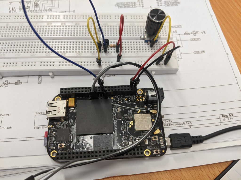
Here is a photo of my my test setup up. I’m using a transistor to drive the LED to avoid pulling too much current from the BBB output pin. Most pins can only supply about 4mA of current.
Now that I could reliably test the output of the existing PWM driver I was finally in a position to start work on adding the eQEP functionality.
More on that in the next post.

Pingback: RTEMS on BeagleBone Black Wireless – Part 2 | Jamesfitzsimons.com
Pingback: RTEMS on BeagleBone Black Wireless – Part 3 | Jamesfitzsimons.com