Overview
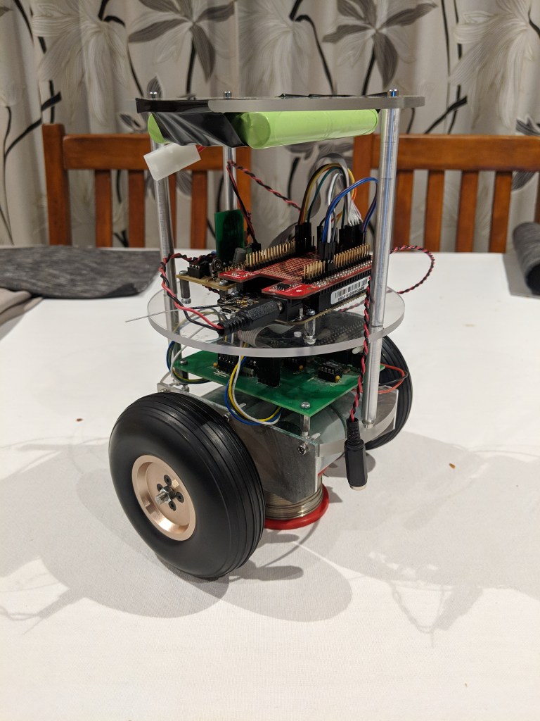
My current robotics research platform is a two wheeled dynamically balancing (inverted pendulum) robot. It is heavily inspired by David P. Anderson’s (aka dpa) nBot. I’d like to thank dpa for documenting his robots so well and for the help he has provided over the years on the Seattle Robotics Society mailing list.
The purpose of the project is to develop a platform on which to test various sensors, navigation and map building algorithms (SLAM), and dynamic control algorithms. Hector is intended to be a stepping stone on a longer term roadmap that includes experimenting with a number of platform designs.
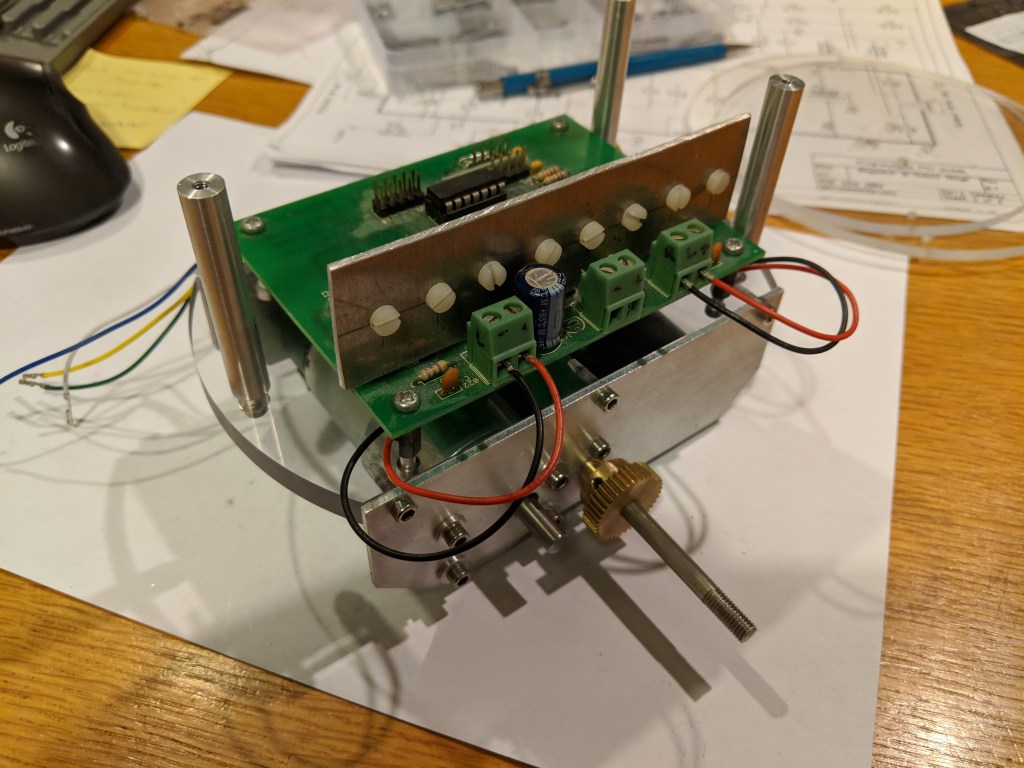
Chassis
Hector has a aluminium and acrylic body. These two materials are reasonably easy to work with but result in a very robust platform. I have a small lathe which I use to manufacture all metal and acrylic parts for my robots.
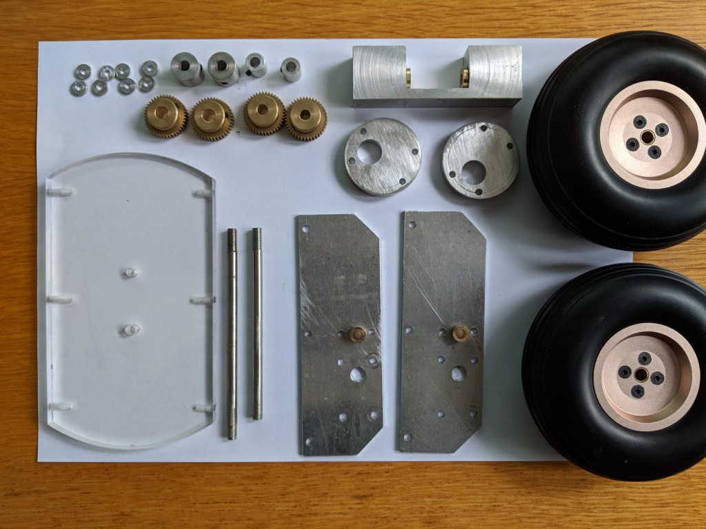


Hectors wheels and gear train are from Aliexpress. The wheels are 4.5″ model air-plane tail wheels. They are very reasonably priced but have aluminium hubs and good quality rubber tires. https://www.aliexpress.com/item/2pcs-Tail-Wheels-Rubber-PU-Alloy-Hub…
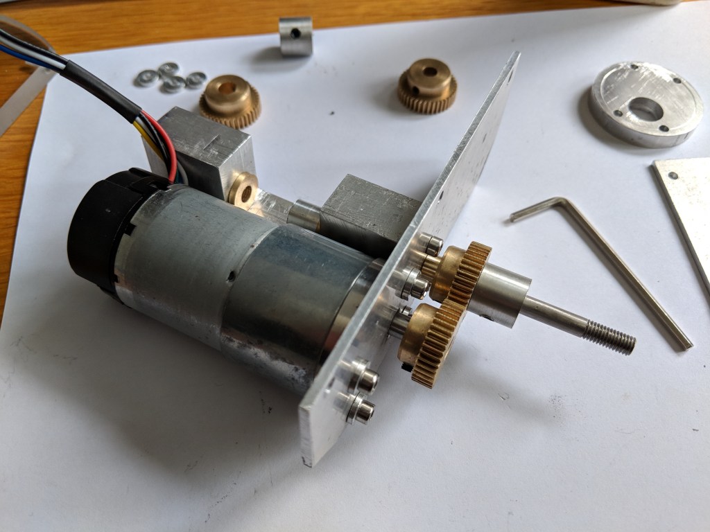
The gear train uses brass gears, again purchased from Aliexpress. 60 tooth brass gears and 20 tooth brass gears
I initially started out with a 1:1 gear ration with 30 tooth gears on both the motor output shaft and wheel shaft. I changed to a 3:1 ratio (60 tooth gear on motor output shaft and 20 tooth gear on the wheel shaft) in an attempt to provide the necessary speed to prevent the robot tipping over after a very small tilt angle.
The motors are DF robot FIT0186 motorsavailable from a number of places on the internet, but I purchased mine from Digikey (Digikey part no. 1738-1106-ND) . I initially started with FIT0403 motors (Digikey part no. 1738-1156-ND) but found the 122RPM output speed wasn’t sufficient, even with the 3:1 gear ratio change. The update to the 251RPM motors has resolved this and the robot is now able to generate enough speed to recover from a reasonable tilt angle.
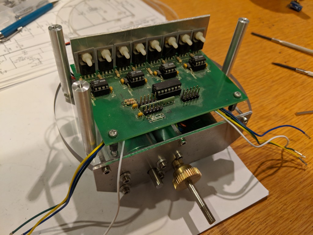
The motor driver board is recycled from my previous robot AMI. This board is an adaption of a design by David Smith. It uses xx yyy drivers and aaasss mosfets to provide dual H-bridges and also includes headers for the encoder outputs from the motors. All the various input and output signals are combined into a single 20 pin header which links the motor driver board with the main robot control board. This is a pretty old design now, but still works fine and is sufficient for my immediate needs.
It needs a better heat-sink solution than the aluminium plate I’m currently using if the robot is to run for long periods of time, particularly if it spends a significant amount of time stationary (balancing in place).
Inertial Measurement Unit
The 9 degree of freedom IMU is neat little board I purchased of eBay. It includes a 3 axis ADXL 345 accelerometer, a 3 axis ITG3205 gyro and 3 axis HMC5883L magnetometer.
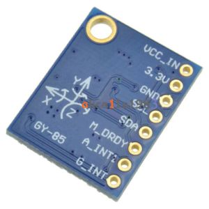

The IMU has far more capability than is required for this simple robot, and at least initially, I am only using the pitch axis on the accelerometer and gyro.
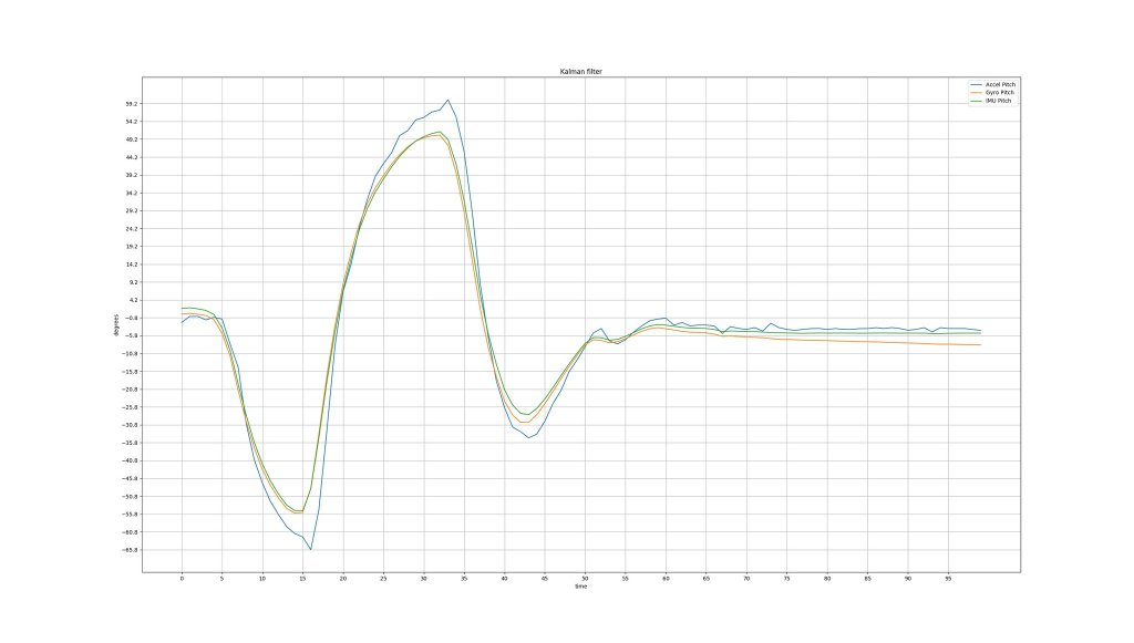
I’m using a basic kalman filter to perform the sensor fusion on the output signals from the gyro and accelerometer. You can see from the graph below that the kalman filter is really effective at smoothing out the noise from the accelerometer and removing the drift from the gyro.
Beaglebone Black Wireless
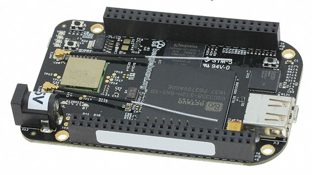
The main control board for the robot is a Beaglebone Black Wireless single board computer. I was initially drawn to the BBBW because of the combination of the reasonably high power application processor and dual real time PRUs. It seems that a lot of people are not even aware of the two 32 bit Programmable Realtime Units (microcontrollers) on the Beaglebone Black, especially when comparing it to other single board computers like the Raspberry Pi. I will be relying on the PRUs to provide the deterministic realtime capability required for things such as the Sonar, IR, or LIDAR sensors I am intending to add to the robot.
The Linux OS is convenient with regards to having out of the box support for all the peripherals, and useful tools like SSH for being able to remotely manage the robot over WIFI.
However, Linux is pretty poor when it comes to realtime control. It’s difficult to write software that runs with deterministic timing, particularly when your requirements are getting down to the low millisecond or sub-millisecond resolution. For a lot of robotics related applications, deterministic timing is a core requirement. For example, my kalman filter implementation needs to be called with a consistent period in order to determine rates of change (e.g. angular velocity from the gyro). Although it is possible to write kalman filters with dynamic timing it is significantly more difficult.
I have managed to get by so far using POSIX timers and signals to run PID loops etc. The robot does occassionally display some erratic behaviour however, and I suspect it is due to another system process taking more CPU than normal and slightly delaying my application timer.
The ideal solution to this would be to abandon Linux completely and switch to a real RTOS such as RTEMS, and this is something I am beginning to investigate. I have the latest RTEMS build running on a second BBBW, however the board support package (BSP) for the Beaglebone is still not particularly complete in terms of peripheral support. I’ve used RTEMS in the past and have dabbled with BSP work for my old MRM 68332 board, so adding some of the missing drivers is something I’m keen to investigate.
