One of the projects I’m currently working on is an adaption of a programmable power supply partially developed by Gerry Sweeney. I say partially developed because although Gerry did an amazing job documenting his fantastic project and creating some great youtube videos, it looks like life got in the way and he never quite finished it. I’m hoping that my attempt at a slightly updated and revised version will result in a completed project.
I’ve decided to start by trying to replicate the digital logic portion of the design as that is the area I am most comfortable with. I would describe myself as an analog novice, so I need to spend some more time digesting that aspect of the design before I attempt that. I’ve also decided to replace the PIC micro-controller with an STM32F070CBT6 as, although I played with PICs many years ago, the ARM architecture really seems like the way forward at the moment, or at least until RISC-V becomes mainstream 😉
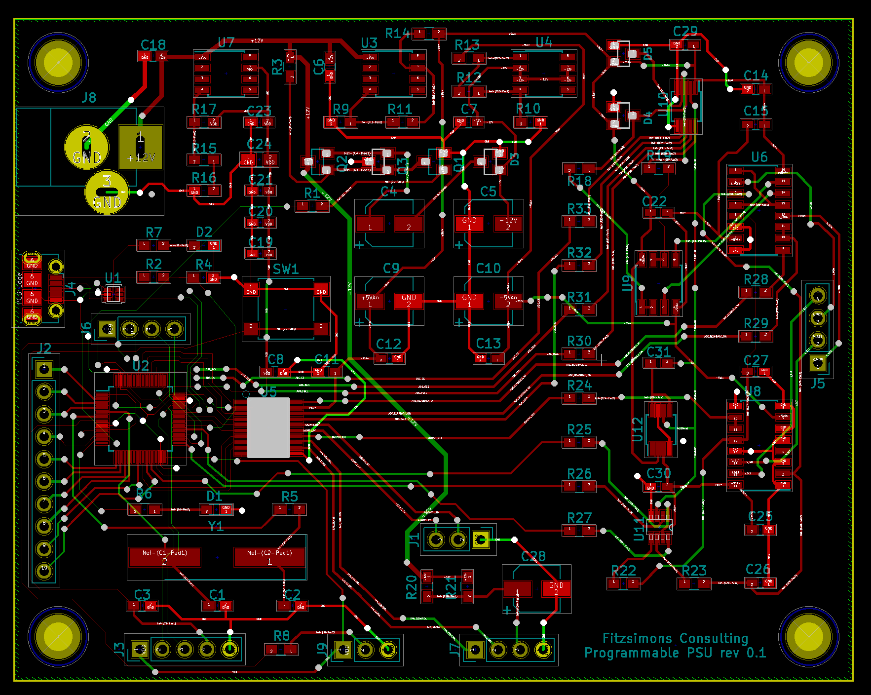
I’ve drawn up the schematic in Kicad, another first for me as my limited PCB design experience in the past has all been with Eagle. I’ve found Kicad pretty easy to use once I worked my way through the tutorial and have found the answers to any roadblocks easily enough with a quick google. The real challenge though has been the layout phase. This is by far the most complicated design I’ve ever laid out from scratch. After spending more evenings than I’d like to admit on getting it laid out, I realised my component spacing is way too tight and there is no way I am going to be able to hand solder this board. So, back to the drawing board and I’m pretty much going to have to lay it out all over again. Lessons learned the hard way often stick with you though, so hopefully this will be the first and last time I make that mistake.

Here is the current schematic. As it’s my first Kicad schematic I haven’t bothered figuring out how to split it across multiple pages yet – hence the A3 size. psu_schematic