A while ago I got the idea to design a small STM32 development board similar to the popular “blue pill”. I had several aims for the project:
- I wanted try out a couple of new parts which I was planning on using on the next revision of the power supply board.
- I wanted to try out JLCPCB for board manufacture
- I was keen to try panelizing a design
- I also wanted to try using a SMD stencil and solder paste. Up until now I’ve hand assembled all my boards and as the part count goes up it does start to get a bit tiresome.
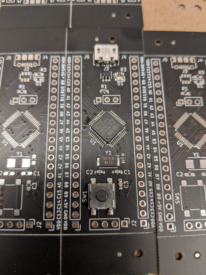
I decided to base the board on the same STM32F070CBT6 part that I’ve been using on the power supply project. It’s a pretty capble part and not too expensive.
I was aiming for a pretty small board size, not wanting to be any bigger than the “blue pill” boards. This combined with the fact that I wanted to bring out every pin on the micro-controller meant that the layout was reasonably tight. Initially I had wanted to keep all the parts on one side of the board but it just wasn’t possible. I ended up putting all the decoupling capacitors and the power regulator on the back side of the board. This helped with the layout issues, but it did make assembly more difficult as a result.
It took me several iterations, but in the end I was reasonably happy with the layout. It probably breaks a bunch of design rules but it seems to work OK. Unfortunately, I must have got distracted in the final stages while I was adding the silk screen for the pin names as about half of them are wrong (copy paste errors). Reminder to self to double check the silk screen labels before sending the next board out!

As mentioned earlier, I ordered the boards from JLCPCB as I was interested in trying their service. I used the “Panelize by JLCPCB” option to panelize the boards and managed to get four boards on the 10 x 10cm board size. I also used the option to get the stencil at the same time. Unfortunately due to COVID 19 delays with the shipping the boards took quite a while to arrive, and stencil didn’t arrive for another week after the boards.

Assembly was pretty straight forward using a hot air reflow. It worked well for these small boards, but I can imagine as the board size gets bigger it would become a less practical technique.
Reflowed using hot air 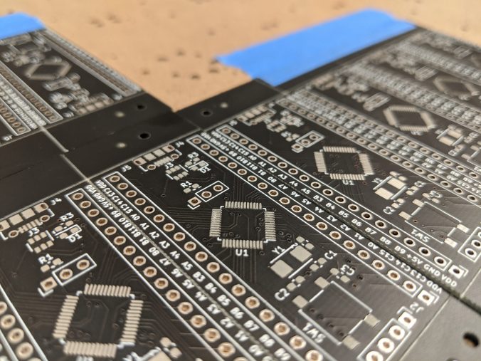
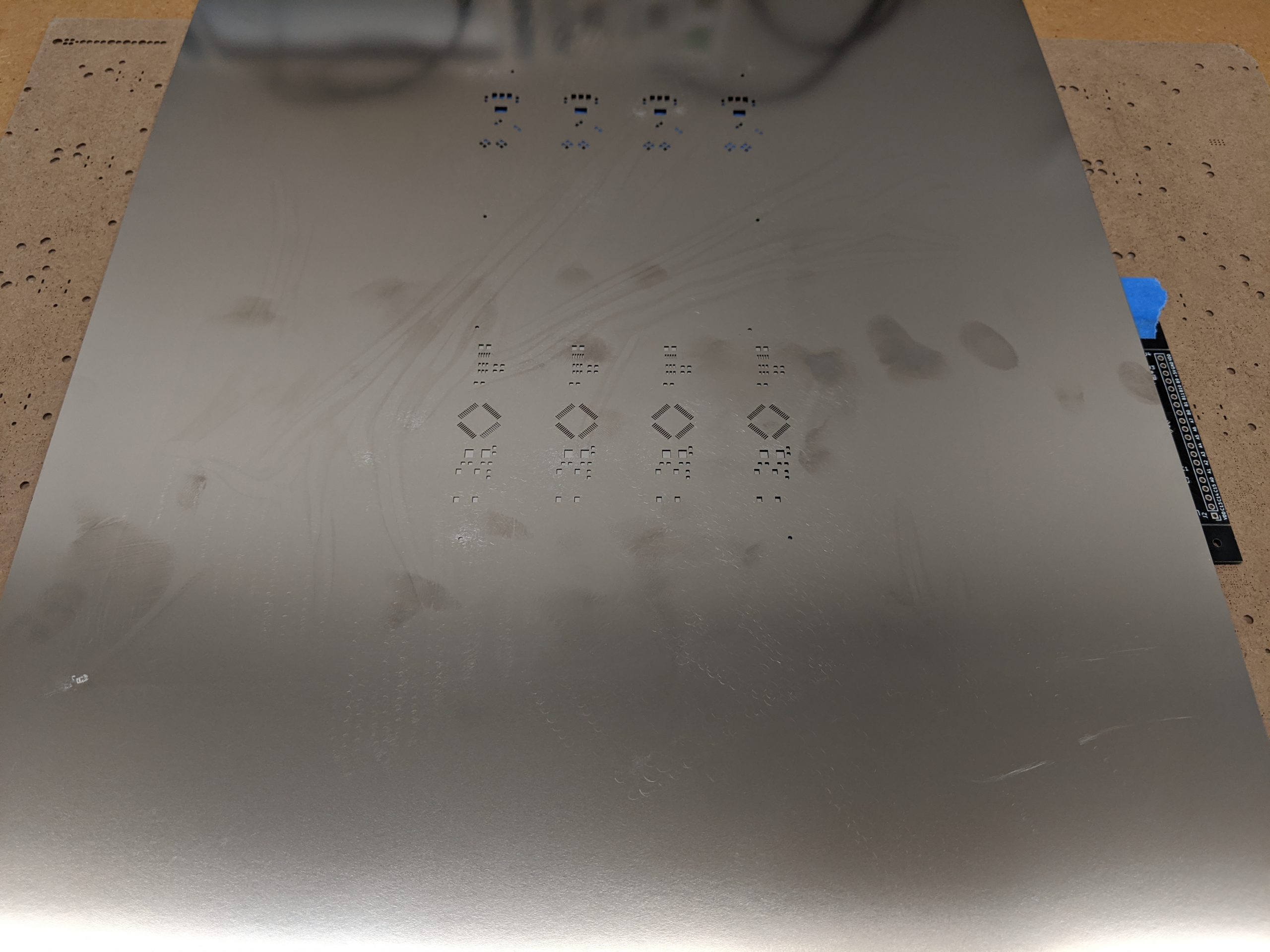
Paste applied using stencil 
Parts placed
I assembled one board just to check that every thing would work and I hadn’t made any layout mistakes. It powers up and programs without issues so there are no obvious issues.
I’ve fixed the silk screen issues and you can get all the kicad files from this repo on gitlab.
https://gitlab.com/jamesfitz/stm32f070-dev-board
Let me know if you use it!
